
A small connection remaining on the edge of die-cut board does not necessarily mean the rule is faulty. Some dies deliberately leave connections that hold components in the sheet during transport. These are produced by nicks in the cutting edge. Distinguishing them from fibres left by an incomplete cut is essential before adjusting the die.
A nick holds the cut component in the sheet
A small nick in the rule prevents the board directly opposite it from being cut through. The remaining connection retains the component during sheet transport or until the separation stage. Its position and purpose are part of the tooling arrangement.
Nick count and width depend on the material, component shape, sheet transport and stripping method. There is no single dimension suitable for every job. A connection needs to survive transport without unnecessarily tearing the component edge when it is separated.
An interruption in the cutting edge is therefore not automatically a defect. The check establishes whether it is intentional and whether the connection performs as required in production.
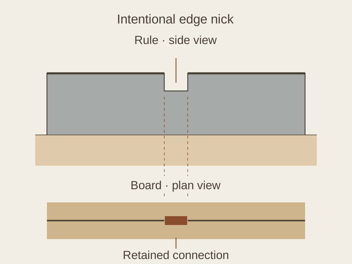
Nick position affects how the component separates
Connection position matters on a long, narrow divider strip. A nick close to a slot entrance, a narrow section or a corner can concentrate the separation load in that region. If the slot edge tears as the connection breaks, its position needs examination.
The same care applies to a connection in the waste inside a divider slot. The intended stage of waste removal matters. If a strip that should be released remains attached, check whether the connection is part of the drawing and the planned stripping arrangement.
How to check a nick mark
The die maker locates the point on the cutting rule that corresponds to the connection on the sample. At a known nick position, the connection is assessed during transport and separation. If there is no nick, the rule joint, seating and local cutting contact are examined.
A mark recurring at the same point is not enough to identify an intentional nick. A gap at a rule joint can repeatedly leave a connection too. The unstripped sample and the die need to be examined together.
Finding a nick does not end the check. Does the connection break too early in the press, resist stripping or tear the edge? These results help establish whether the nick arrangement is suitable.
| Sample finding | What to check |
|---|---|
| Small connection at a known nick | Does it hold during transport and separate cleanly? |
| Unwanted connection at a rule joint | Is there a gap or a difference in cutting-edge height? |
| Uncut fibres along an extended line | Is the rule seated correctly and reaching the cutting surface? |
| Edge tears as the connection breaks | Are the position, size and separation direction suitable? |
Gaps at rule joints
A gap where two steel rules meet, or a mismatch in cutting-edge height, can leave a small connection in the board. It may resemble a nick mark on the component. If there is no intentional nick at that position, the connection is investigated as an incomplete cut.
Check the joint and rule seating before increasing pressure. Loading the whole die more heavily to correct one small area can cause unnecessary marks and wear where cutting is already satisfactory. Pulling the component free more forcefully does not correct the tooling fault.
Why an unstripped sample matters
A single component with an edge tidied by hand does not show exactly how it left the die. An unstripped sheet alongside the separated component preserves the original connection and the mark left when it breaks.
In a repeated layout, mark the affected position on the sample. Clean cutting in the other positions helps narrow the check to local rules and nicks. If every component tears in the same way, examine the shared geometry, material and separation method.
Divider components must subsequently interlock, so any protrusion or tear also needs checking for its effect on fit. A connection may hold well during transport yet damage the component during separation. In that case, the nick arrangement needs further assessment.
Planning nicks for a new die
A drawing of the outer contour and interlocking slots does not fully describe how components will be held throughout production. The press, board and stripping method are considered when choosing nick positions.
When replacing a divider die, samples from the previous run show useful details. Connections that separate cleanly can be marked alongside those that tear an edge or break too early. This gives the die maker a practical basis for planning the new nick arrangement.


